
Transom Mount Installation on a Fiberglass Boat
Learn what a transom mount means, how loads differ, when damage stops the job, and how to place and seal hardware correctly on a fiberglass boat.
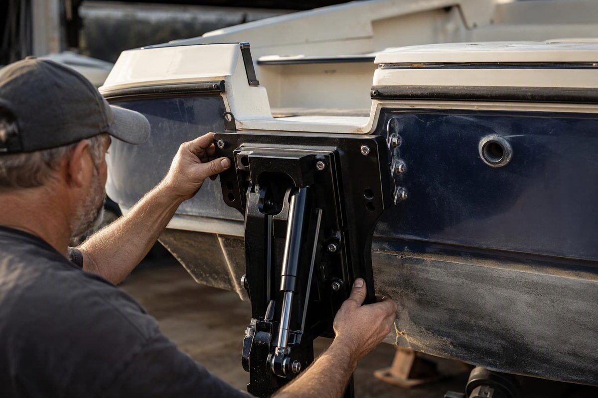
A transom mount is hardware attached to a boat’s stern structure, but there is no universal installation method. A clamp-on trolling motor, screw-mounted sonar transducer, shallow-water anchor bracket and main outboard impose different loads. Identify the equipment, follow its model-specific instructions and determine whether the transom is solid laminate or fiberglass skins over a wood or foam core before selecting fasteners or drilling.
Select the equipment, visible condition and transom construction to see the appropriate next step.
Transom Mount Decision Check
Use the visible condition as a stop check before choosing an attachment method.
Inspect the construction before drilling
Current next step: Follow the transducer’s template and placement instructions, but first establish whether drilling will expose a core. Garmin’s general guidance calls for clean water flow and at least 15 inches (38 cm) of propeller separation; the model manual controls.
Sources: Garmin transducer guidance, Minn Kota Endura instructions, Epoxyworks transom repair guidance and the WEST SYSTEM fiberglass repair manual.
Match the Attachment to the Equipment
| Equipment | Typical Attachment | Main Concern |
|---|---|---|
| Small trolling motor | Clamp-on bracket | Crushing, slipping and clearance |
| Sonar transducer | Small screws or mounting plate | Clean water and sealed holes |
| Larger accessory bracket | Specified through-bolts and backing | Concentrated dynamic load |
| Main outboard | Builder-approved installation system | Structural and propulsion loads |
Install a clamp-on motor as its manufacturer intends rather than converting it to a screw attachment. Minn Kota’s Endura instructions place the bracket over an unobstructed section of the transom and specify tightening the clamp screws only with your hands. Tools can damage the bracket or boat. The instructions also require clearance for the control box, handle and propeller throughout the steering range (Minn Kota).
Those directions apply to the Endura models covered by that manual. Use the instructions for the actual motor rather than copying dimensions or torque from a different mount.
An outboard or high-load anchor bracket is not a larger version of a transducer installation. Outboard weight is compounded by acceleration and trailering loads concentrated at the transom skin and core (Epoxyworks). Installation and hole changes should follow the boatbuilder’s and equipment manufacturer’s specifications. Consult a marine surveyor or qualified installer if the structure, required backing or previous alterations are uncertain.
Stop When the Transom Shows Movement or Moisture
Inspect the transom’s outer face, inner face and top edge before covering the area with hardware. Stop the installation if you find:
- flexing or relative movement between the transom and adjoining structure;
- cracks radiating from motor bolts, drain tubes, cutouts or corners;
- brown liquid, wet debris or dark core material at an existing hole;
- crushed laminate beneath washers or clamp pads;
- hardware that will not remain secure; or
- a dull area during comparative tap testing, particularly when another warning sign is present.
Tap testing is comparative and does not prove that a transom is sound. Intact gelcoat also does not establish that the core is dry. Epoxyworks notes that water can enter plywood-cored transoms through fasteners, drains and cutouts. Excessive motor movement can be an early sign that the structure has lost stiffness (Epoxyworks).
Repair wet, soft or delaminated structure before adding another mount. The boat fiberglass hull guide explains the roles of fiberglass skins, reinforcement and core.
Position a Transducer in Clean Water
A transducer must remain in clean, non-aerated water while avoiding impact and propeller hazards. Garmin’s general guidance says to keep it away from strakes, steps, fittings, intakes and discharge ports. It should sit parallel to the waterline and outside areas vulnerable during launching, hauling or trailering.
The same guidance calls for at least 15 inches (38 cm) of separation from the propeller. That is general Garmin guidance; the product manual controls placement for a specific transducer (Garmin Support).
Before drilling:
- Hold the actual bracket and cable route in position.
- Check steering, trim, trailer-bunk and tie-down clearance.
- Inspect behind the transom for wiring, hoses, tanks and inaccessible voids.
- Confirm that each penetration can be sealed and inspected later.
- Mark holes from the supplied template, not a similar-looking bracket.
When placement remains uncertain, a bonded transducer mounting board may permit later bracket changes without repeatedly drilling the transom. The board’s adhesive and surface preparation still must suit the gelcoat, laminate and expected load.
Seal Gelcoat and Core as Separate Problems
Wear eye, hearing and respiratory protection when drilling or sanding fiberglass. Verify what is behind the surface before drilling. For a small screw-mounted transducer, use the bit diameter and hole depth specified in its instructions. Tape can reduce surface chipping, while a depth stop can prevent an accidental through-hole.
Garmin’s transducer instructions recommend a shallow clearance counterbore through only the gelcoat where screws enter fiberglass. The counterbore helps prevent the brittle finish from cracking as the screws tighten. The instructions also call for marine sealant on the screws and a leak check after launching (Garmin installation instructions).
A gelcoat counterbore does not protect an exposed core. For a through-bolted fitting on a cored panel, one established method is to remove core locally around each penetration, fill the cavity with structural thickened epoxy, allow it to cure and redrill through the cured epoxy. The epoxy annulus helps distribute compression loads while isolating the core from moisture.
The WEST SYSTEM fiberglass repair manual describes this method and calls for repairing existing core damage before reinstalling hardware (WEST SYSTEM).
Do not apply the epoxy-annulus procedure indiscriminately to every screw hole. Hole geometry, filler, backing plate, fastener size and cure requirements depend on the substrate and load. Cosmetic fairing putty is not a substitute for a load-bearing epoxy mixture; choosing a 2-part epoxy filler explains the distinction.
Sealant beds the completed joint. A properly specified epoxy-filled annulus supports the penetration and isolates exposed core. The two are not interchangeable. Check sealant compatibility with plastics, paint and removable hardware because a strong adhesive sealant can make later service destructive.
Test the Mount Before Relying on It
After the specified cure and final assembly, inspect for gelcoat cracking, clamp indentation and hardware movement. Launch the boat and check every new penetration for leakage before leaving it afloat.
Test a transducer at low speed. Increase speed gradually while watching the bottom return, then make only the small adjustments permitted by its manual (Garmin installation instructions).
Reinspect the installation after the first outing and periodically thereafter. Minn Kota recommends checking its transom-motor clamp screws, bracket and depth collar before and after each use (Minn Kota maintenance guidance). Recurring looseness, a fresh crack, dampness or movement is a stop signal, not a reason to fit a larger screw.