
7 Steps to Adjust and Test Your Screen Door Closer
A 1/8-turn starting change and clockwise-to-slow direction apply to many pneumatic screen door closers, but neither rule is universal.
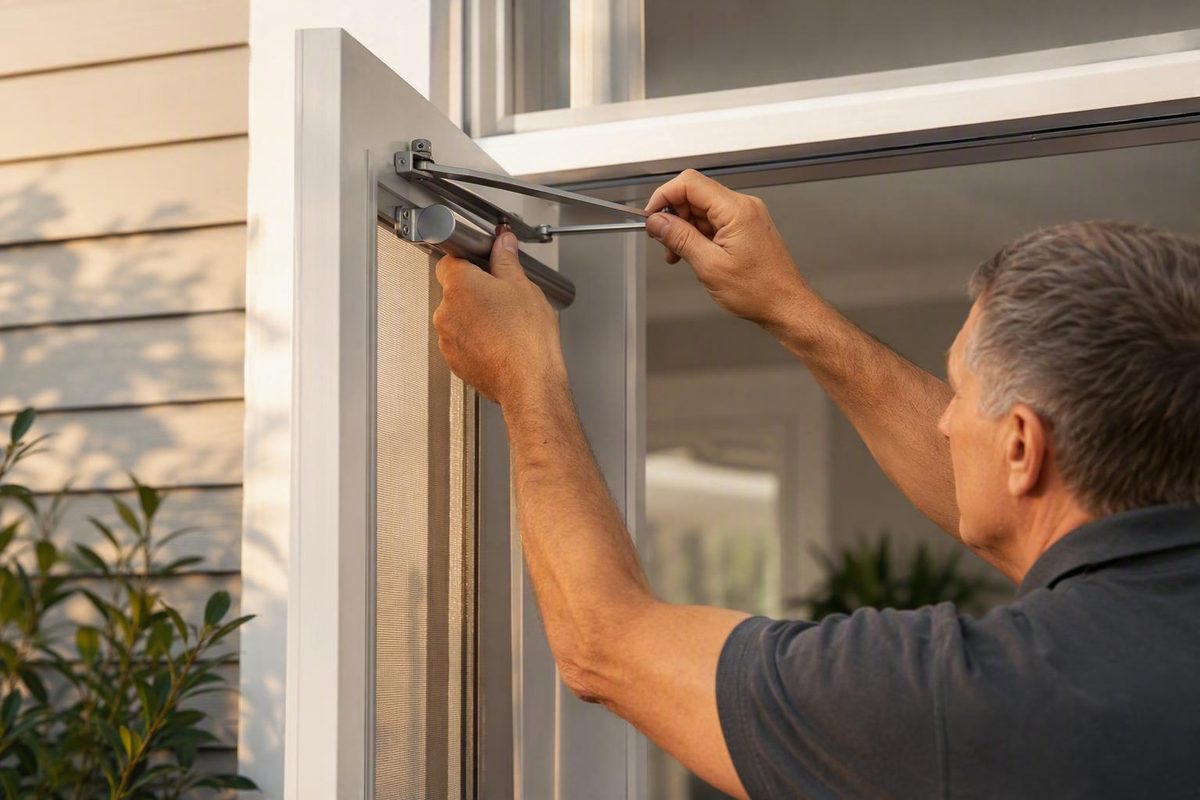
A successful screen door closer adjustment does two things: it controls the door through its full swing without slamming, and it leaves enough closing action for the latch to engage. Turning the speed screw may solve the problem, but first identify the closer and rule out loose, worn, binding, or misaligned hardware.
Most residential pneumatic closers follow a similar adjustment pattern. Even so, closing speed, spring force, bracket geometry, latch alignment, and seasonal pin position are separate variables. Check the closer’s label or manufacturer instructions before relying on a generic turning direction.
Quick answer: which way should you turn the closer screw?
For many pneumatic screen- and storm-door closers:
| Door behavior | Common adjustment | Conservative starting change |
|---|---|---|
| Door slams or closes too fast | Turn clockwise to increase airflow resistance and slow it | About 1/8 turn |
| Door closes too slowly | Turn counterclockwise to reduce resistance and speed it up | About 1/8 turn |
| Door moves at a reasonable speed but will not latch | Inspect alignment, hinges, brackets, and latch hardware before assuming speed is the problem | Test the existing setting first |
The one-eighth-turn starting point and clockwise-to-slow direction apply to many pneumatic models, not every closer. Test after each change and follow the direction marked on the cylinder whenever it differs from this chart (AKADA’s pneumatic closer guide).
Do not make several turns before testing. Some general procedures use quarter-turn adjustments, but that is better treated as a maximum step than as a reason to make a large initial correction (RiteScreen’s closer-adjustment guide).
Judge the result by more than noise. The correct setting produces smooth, controlled travel followed by complete latch engagement. A door that closes quietly but stops against the latch is not fully adjusted.
Also avoid treating the screw as a universal tension control. On a typical pneumatic closer, the screw primarily regulates airflow resistance and closing speed. It does not necessarily strengthen the internal spring or correct insufficient final-latch force.
Identify the closer before making an adjustment
Before reaching for a screwdriver, determine which mechanism is attached to the door.
Single pneumatic closer
A pneumatic closer normally looks like a narrow cylinder connected between the moving door and the jamb. Opening the door moves a piston and compresses an internal spring. When the door is released, the spring returns the piston while restricted airflow moderates its movement.
Locate the following parts:
- Cylinder or barrel: The main tubular body
- Piston rod: The rod that extends from the cylinder
- Door bracket: The fitting attached to the moving door
- Jamb bracket: The fitting attached to the frame
- Connecting pin: The removable pin used at some bracket connections
- Adjustment screw: Usually located near one end of the cylinder
- Hold-open washer or button: A device found on compatible models
The screw’s exact location varies. On one documented residential design, it is at the door-side end of the barrel, and that model’s instructions call for the closer to be unhooked before adjustment (All About Doors’ pneumatic closer instructions). Do not assume that location or disconnection requirement applies to every cylinder.
Traditional exposed spring closer
A traditional closer may consist mainly of an exposed tension spring running between the door and frame. It does not use the pneumatic airflow adjustment described in this guide.
Its tension is changed by repositioning the spring’s hook or anchor. That directly changes spring tension, unlike turning the speed screw on a pneumatic cylinder.
Dual pneumatic closers
Some storm doors have two cylinders, commonly mounted near the top and bottom. Do not turn both screws at random or assume that every dual system uses the same procedure.
The alternating method described later—disconnecting and adjusting each cylinder independently—is documented for specified Andersen and EMCO push-button and hold-open closer arrangements. Other manufacturers may prescribe a different order, tool, or testing method.
Seasonal two-hole closer
Inspect the connection between the closer and the door bracket. Some systems provide two pin holes so the mounting geometry can be changed when switching between a glass panel and a screen.
Seasonal pin instructions apply only when the closer has the corresponding two-hole arrangement and the product documentation identifies the positions. Do not infer the correct hole from an unlabeled bracket that merely looks similar.
Pneumatic versus hydraulic hardware
Pneumatic and hydraulic are not interchangeable terms. Pneumatic closers use controlled airflow; hydraulic closers use fluid control and may be used for heavier or higher-traffic applications.
This guide concerns lightweight residential pneumatic cylinders and traditional screen-door springs. It does not cover specialized commercial, heavy-door, or fire-rated closer systems.
If the design is unclear, look for a brand, model number, directional arrow, or “faster/slower” marking. Manufacturer documentation should take priority over advice based only on the closer’s appearance.
Inspect the door, hinges, and brackets first
A closer cannot reliably compensate for a door that binds, sags, or meets a misaligned latch. Before changing the valve setting, open and close the door while watching the entire mechanism.
Check:
- Door-bracket and jamb-bracket mounting screws
- Connecting pins and their holes
- Hinges for drag or restricted movement
- Alignment between the latch and strike
- Brackets that have shifted or begun pulling away
- Whether the cylinder and piston rod move in a straight line
- Loose or worn connections around the brackets
- Visible dents, bends, cracks, or other cylinder damage
- Sticking, hesitation, or jerky piston movement
- Visible leakage or an inability to regulate closing speed
Do not diagnose normal operating noise alone as an air leak. A pneumatic closer moves air internally, so uncertain sounds should be evaluated against the model’s instructions and actual performance. Visible fluid leakage may indicate hydraulic or unfamiliar hardware outside this procedure.
The cylinder should extend and retract without being forced sideways.
Watch the final part of the swing closely. If the door reaches the frame but the latch and strike meet in the wrong place, the likely problem is alignment rather than speed. If the door slows substantially before reaching the frame, hinge drag, bracket geometry, or excessive pneumatic resistance may be involved.
Use the screwdriver that fits the actual adjustment screw. Documented designs vary between flathead and Phillips screws, and some model-specific dual-closer instructions identify pliers for their connecting pins. Do not assume one tool fits every closer.
Lubrication is also model-dependent. Do not introduce lubricant into a sealed pneumatic cylinder. Lubricate an exposed pivot only where the manufacturer identifies both the location and an appropriate product; supplier guidance likewise distinguishes permitted pivot maintenance from lubricating the sealed air cylinder (AKADA’s maintenance guidance).
Finally, determine whether the closer is adjusted while connected or disconnected. Some product instructions call for unhooking a particular connection, while other closers can be adjusted in place. If disconnection is required, follow the exact manufacturer procedure for controlling the door and handling the connection. Do not improvise pin removal without model-specific instructions.
How to adjust a single pneumatic screen door closer
Once the hinges, brackets, fasteners, and latch appear secure and aligned, use this sequence for a typical single-cylinder pneumatic closer.
1. Secure the door as directed
Open and secure the door using its intended hold-open feature or the method specified by the manufacturer. Do not begin disassembling a bracket merely to gain easier access to the screw.
Locate the adjustment screw, commonly found near one end of the cylinder.
2. Read the closer label
Look for:
- Faster and slower markings
- Directional arrows
- A brand, model, or series number
- Instructions about disconnecting the closer
- A specified adjustment increment
- Any warning against turning the screw beyond a stated limit
If the label contradicts the common clockwise-to-slow rule, follow the label. If the markings are unreadable, locate the model instructions before making repeated changes.
3. Disconnect the closer only when specifically instructed
Do not apply a universal disconnection rule. If the product instructions require the closer to be unhooked, follow their exact procedure and remove only the connection they identify. One documented door-side design, for example, instructs the user to unhook the closer before adjusting its end screw (All About Doors’ model-specific procedure).
If you cannot identify the model or find its connection procedure, leave the hardware assembled and seek manufacturer guidance rather than improvising.
4. Make one small correction
For a door that slams, use the conservative starting change shown in the quick-answer chart if the closer confirms that clockwise is the slower direction.
For a door that closes too slowly, make the corresponding small counterclockwise change only if the model identifies that as the faster direction.
Use the screw slot or cross as a visual reference so you can track the direction and size of the change. Do not make several adjustments before testing.
5. Restore any model-required connection
If the manufacturer’s procedure required disconnection, restore the closer exactly as directed before testing. Confirm that the connection is in its original documented position unless you are intentionally following a supported seasonal pin-position procedure.
6. Test from normal opening positions
Release the door from an ordinary opening angle and watch its full travel. Repeat from another normal position. A closer can behave differently when released from a narrow opening than when the piston has been extended farther.
Observe:
- Initial closing movement
- Speed through the middle of the swing
- Movement near the latch
- Slamming or abrupt acceleration
- Pauses, sticking, or erratic travel
- Complete latch engagement
Do not judge the adjustment from one unusually wide or narrow opening alone.
7. Repeat only as needed
Continue with the same small correction only while the closer responds predictably and the door’s operation improves.
If the change produces the opposite result, stop applying the generic turning rule and consult the model instructions. If the screw has little or no effect, investigate binding, misalignment, wear, or closer failure instead of making progressively larger changes.
How to adjust and synchronize two storm-door closers
The following is the documented Andersen or EMCO approach for supported dual push-button and hold-open closer configurations. It is not a universal procedure for every door with two cylinders.
For applicable systems:
- Follow the manufacturer’s instructions to disconnect the bottom closer.
- Operate the door using the top closer alone.
- Adjust the top closer in quarter-turn intervals, testing after every change.
- Reconnect the bottom closer as directed.
- Follow the instructions to disconnect the top closer.
- Operate the door using the bottom closer alone.
- Adjust the bottom closer in quarter-turn intervals, testing after every change.
- Reconnect both closers.
- Test the complete system for the preferred speed and full latching.
- If further correction is needed, make equal changes to both adjustment screws.
For these documented Andersen configurations, counterclockwise makes the door close faster and clockwise makes it close more slowly. The manufacturer identifies a Phillips-head screwdriver and pliers for the procedure (Andersen’s dual-closer speed-adjustment instructions).
Turning both together from the outset can hide that imbalance. After both work properly by themselves, equal follow-up changes help preserve synchronization.
If your dual-closer door is not an Andersen or EMCO configuration covered by those instructions, use its manufacturer’s sequence. Do not assume its connecting pins, tools, adjustment increments, or disconnection order are identical.
Closing speed, latch force, and seasonal pin position are different adjustments
Many unsuccessful adjustments begin with treating speed, tension, pressure, and force as interchangeable terms. Several distinct factors determine how the door behaves.
Closing speed
The pneumatic screw primarily changes how freely air moves through the closer. More resistance generally slows the piston; less resistance generally allows it to return faster.
This is the appropriate variable to adjust when a correctly aligned door clearly moves too fast or too slowly.
Closing force
The internal spring supplies most of the energy that returns the door. Effective closing force is also influenced by closer size, mounting position, and bracket geometry.
Changing the speed screw may determine whether the door carries enough movement into the latch, but it does not necessarily make the spring stronger. For that reason, instructions to “turn the screw to add pressure” can be misleading.
Final-latch action
A slowly closing door that stops short may have excessive airflow resistance. Reducing resistance slightly can help when the model confirms the appropriate direction.
Incomplete latching can also result from:
- Hinge drag
- A shifted door or jamb bracket
- Loose mounting screws
- Side-loading or binding of the piston rod
- A latch and strike that no longer align
- Worn connecting pins or holes
- An unsuitable or incorrect mounting position
If the travel speed already looks reasonable, inspect these conditions before opening the valve farther.
Seasonal two-hole pin position
For the compatible two-hole design documented by Family Handyman:
- The hole identified as the front hole nearest the door bracket is used with the winter glass-panel configuration.
- The hole identified as the rear hole farther from the door bracket is used with the summer screen configuration.
On that design, the nearer position increases closing pressure during the final part of the swing to help the latch engage, while the farther position slows the approach to the catch (Family Handyman’s seasonal two-hole guide).
Those terms can be difficult to apply without the source’s illustration. Do not infer “front” and “rear” from this description alone if your bracket is oriented differently or lacks matching documentation. Seasonal pin placement changes the closer’s geometry; it is not simply another speed-screw setting.
Traditional spring tension
An exposed spring closer uses a different adjustment. On the documented spring design, moving the hook one anchor hole closer increases tension, while moving it one hole farther away reduces tension (RiteScreen’s spring-closer guidance).
Use the correct term for the change being made:
- Speed: Controlled primarily by pneumatic airflow resistance
- Spring tension or force: Supplied by the spring
- Final-latch behavior: Influenced by speed, force, alignment, and geometry
- Seasonal pin position: A mounting-geometry change on compatible designs
Troubleshooting by symptom
When the first adjustment does not solve the problem, use the door’s behavior to decide what to inspect next.
| Symptom | First response | What to inspect if it continues |
|---|---|---|
| Door slams | Make a small clockwise change only if the model identifies clockwise as slower | Direction marking, brackets, pins, mounting screws, cylinder response |
| Door closes very slowly | Make a small counterclockwise change only where the model identifies that as faster | Hinge drag, angled cylinder, shifted brackets, sticking rod |
| Door will not latch | Reduce resistance slightly only if the door is clearly losing movement before the latch | Latch alignment, hinges, bracket geometry, mounting hardware |
| Movement is jerky or sticking | Stop making repeated speed changes | Cylinder, rod, pivots, connections, bracket alignment, visible damage |
| Bracket is pulling away | Stop treating it as a valve-setting problem | Loose or damaged mounting condition |
| Screw has little effect | Confirm the model’s direction and test one small change | Wear, binding, incorrect procedure, closer failure |
| Setting will not hold | Recheck the installation and model instructions | Internal wear or failure |
Slamming
Confirm that clockwise is the slower direction for the model, then make one small change. If the adjustment barely affects closing speed, do not keep tightening indefinitely. Check whether the cylinder is angled, the brackets have shifted, or the closer is worn.
Very slow closing
Reduce resistance slightly where the instructions permit it. If that has little effect, determine whether the door itself moves freely. Hinge drag or a misaligned bracket can slow the door independently of the valve setting.
Failure to latch
Watch exactly where the movement stops. If the door reaches the frame but the latch and strike do not meet, assess alignment rather than increasing speed.
If the door loses movement immediately before the latch, a small model-approved speed change may help. Bracket position, hinge drag, and available spring force still need to be considered.
Jerky or sticking movement
Erratic movement is not simply “too fast” or “too slow.” Inspect the rod, cylinder, pivots, connecting points, and bracket alignment. Repeated valve changes may mask the symptom without correcting the binding.
Bracket pulling away
A loose or separating bracket is a mounting problem. Stop adjustment and identify the damaged or loose condition.
There is no universal repair method for pulled-out brackets or damaged mounting holes. The appropriate response depends on the door, frame material, hardware, and extent of the damage.
Adjustment will not hold
Visible damage, sticking, weak or jerky travel, inconsistent latching, and an inability to retain a setting are reasons to consider replacement or manufacturer service.
Performance can vary with operating conditions and may require later readjustment. Do not assume that a particular temperature change requires a predictable number of screw turns.
Hydraulic closers may be used for heavier or higher-traffic applications, but they fall outside this residential pneumatic procedure.
When adjustment is no longer the right fix
A responsive closer on a freely moving, aligned door is a reasonable adjustment candidate. A damaged or inconsistent mechanism may not be.
Consider replacement or model-specific service when you observe:
- Abnormal air leakage documented for the model
- Visible fluid leakage from hydraulic or unfamiliar hardware
- A sticking piston or rod
- Weak, irregular, or jerky closing
- Visible cylinder damage
- Worn pins, holes, or other connections
- Repeatedly inconsistent latching
- An adjustment that will not remain stable
- Little or no meaningful response to the screw
These symptoms do not prove that the cylinder is the only problem. First verify that mounting screws are secure, brackets have not shifted, hinges move freely, and the latch is aligned. A new closer will not correct a binding door or a misplaced strike.
When replacement is appropriate, match the closer to the door’s size and weight rather than choosing solely by appearance (ALLWIN’s closer-selection overview). Also follow the replacement manufacturer’s stated application limits for traffic and exposure.
Seek manufacturer support when:
- No label or model can be identified
- The observed adjustment direction conflicts with the generic rule
- The screw reaches an apparent limit without solving the problem
- The closer has an unfamiliar pin or bracket arrangement
- A dual-closer system does not match the documented Andersen sequence
- The instructions address leakage or internal service differently
Do not assume that a leaking sealed cylinder can be repaired. Conversely, do not declare every leak universally unserviceable without checking the manufacturer’s instructions. Bent rods, corrosion, stripped mounting holes, and pulled-out brackets also require hardware- and material-specific decisions rather than an unsourced universal repair.
The practical decision rule is:
- Adjust when the hardware is aligned and the closer responds normally.
- Investigate the installation when movement binds or the door misses the latch.
- Consider replacement or model-specific service when the closer leaks abnormally, sticks, is visibly damaged, moves erratically, or cannot retain its setting.
Frequently asked questions
Which way do I turn a screen door closer to stop it from slamming?
For many pneumatic closers, turn the adjustment screw clockwise to increase airflow resistance and slow the door. Make only the conservative starting change shown in the quick-answer chart, then test.
The closer’s label takes priority. If the change has little effect, inspect the hinges, brackets, connections, and cylinder alignment instead of continuing to turn the screw.
How much should I turn the closer adjustment screw at one time?
For a typical single pneumatic closer without a different model-specific instruction, start with about one-eighth turn and test. Avoid making a large correction before observing the result.
Certain manufacturer procedures specify different increments. The documented Andersen dual-closer sequence, for example, uses quarter-turn adjustments while each closer is tested independently.
Why does my screen door close slowly but fail to latch?
The closer may have too much airflow resistance, but the door may also be encountering hinge drag, a shifted bracket, an angled cylinder, loose hardware, or a misaligned latch.
Watch the final portion of the swing. If the latch and strike do not line up, changing speed is unlikely to correct the underlying problem. If the door simply loses movement before reaching the latch, try one small model-approved speed change and inspect the hardware.
Do I need to disconnect the screen door closer before adjusting it?
Only when the model’s instructions require it. Some documented pneumatic designs are disconnected from the door bracket before adjustment, while others can be adjusted in place.
Do not improvise removal of a connecting pin. Follow the exact manufacturer procedure for the closer. Supported Andersen or EMCO dual systems require one cylinder to be disconnected while the other is adjusted independently.
When should a pneumatic screen door closer be replaced?
Consider replacement or model-specific service when the closer sticks, has visible damage, moves weakly or erratically, has worn connections, does not respond meaningfully to adjustment, or cannot retain its setting.
Before replacing it, verify that the hinges, latch, brackets, pins, and mounting screws are secure and aligned. The final check is simple: identify the closer and follow its label, adjust the speed screw in small tested increments, and judge success by both smooth travel and complete latching.